

Search
Search
Phased Array Ultrasonic Testing (PAUT) is based on the same physics as the Conventional Ultrasound inspection. The differences are mainly the probe technology and configuration as well as the acquisition instrument electronics. A Phased Array probe typically consists of 16 to 128 individual elements and can be customized to include more or fewer elements. The elements can also be arranged in linear, matrix and annular patterns.
Possible Phased Array configurations are dependent on what the probe and electronics are capable of. Each element is controlled individually, therefore allowing for the generation of a customized ultrasound beam using a defined delay.
Depending on the inspection requirements, it is possible to optimize each of the essential parameters, such as angular opening, beam orientation, focusing, sectorial scanning and linear scanning.
Advantages :
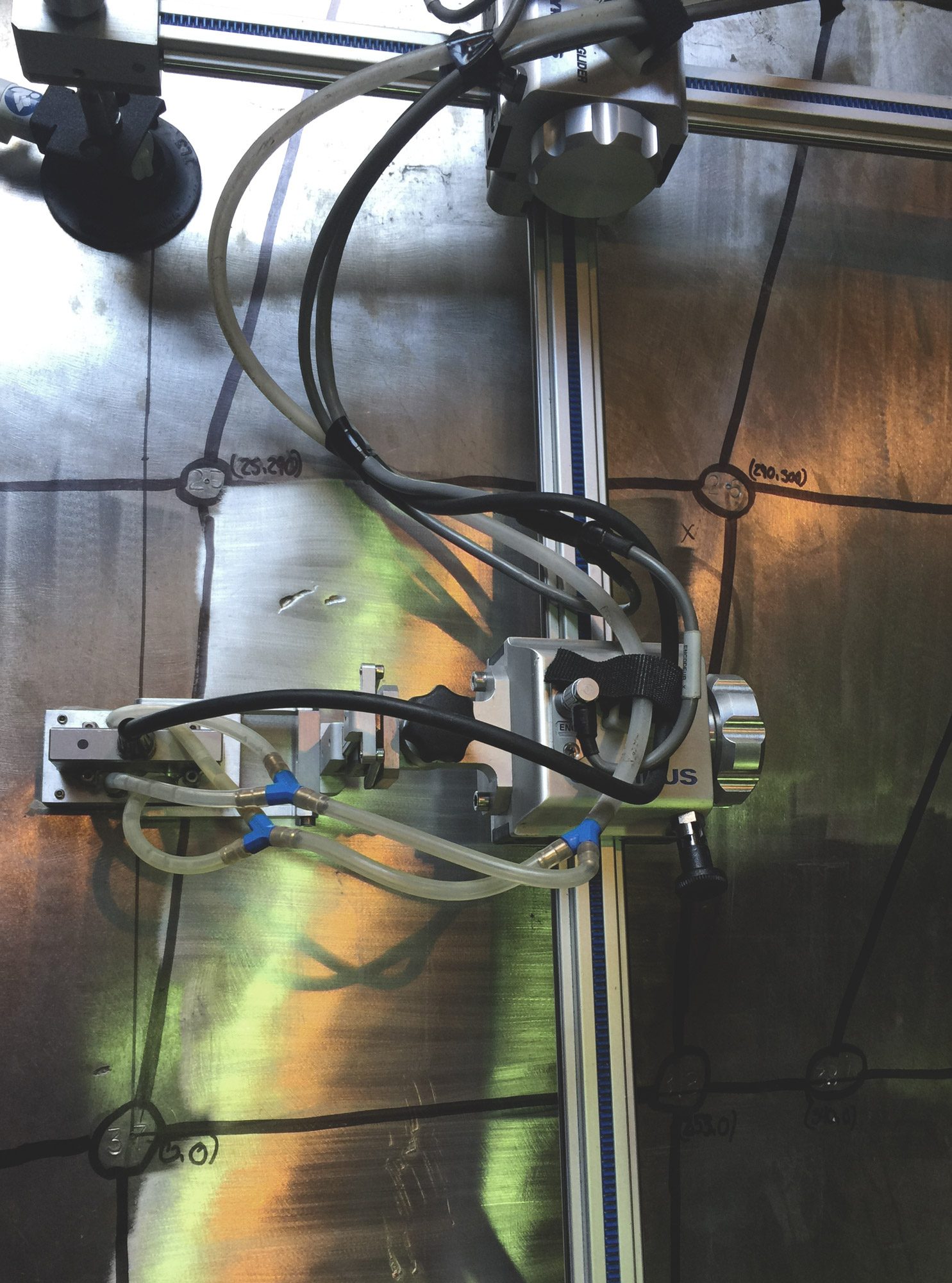
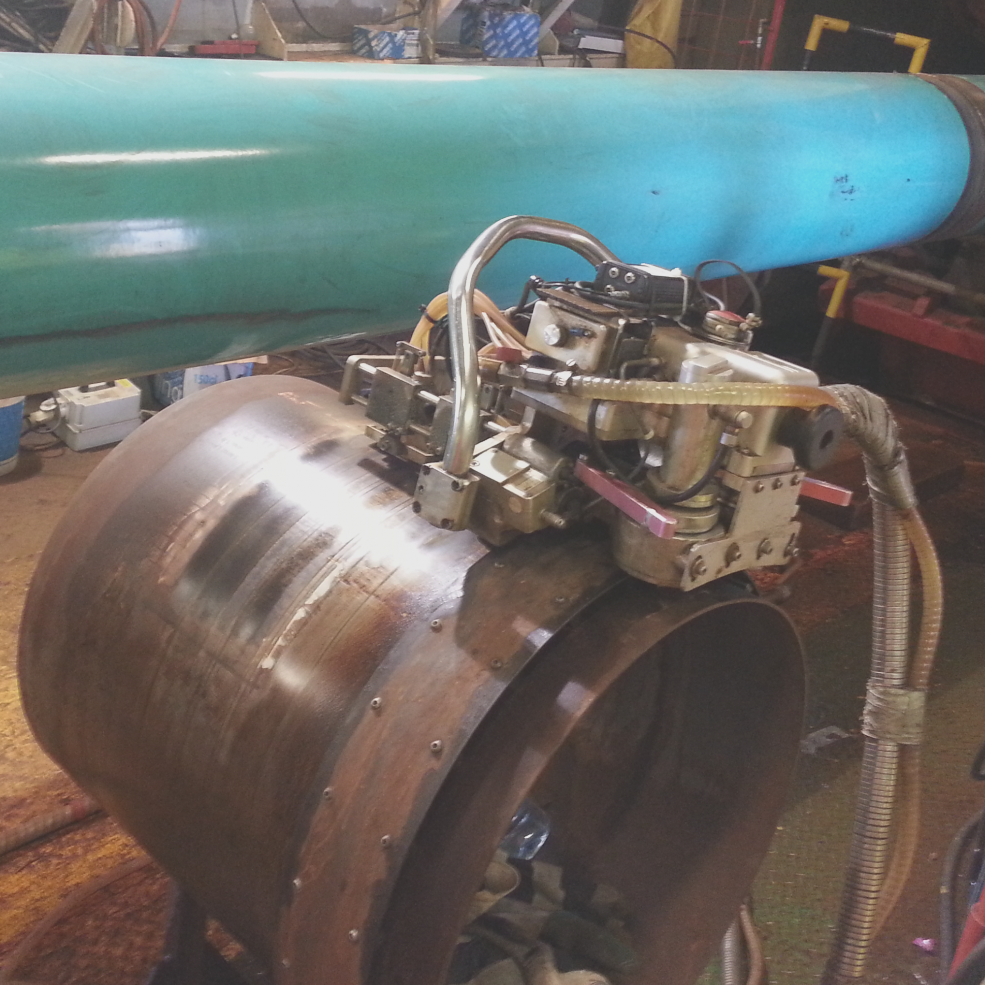
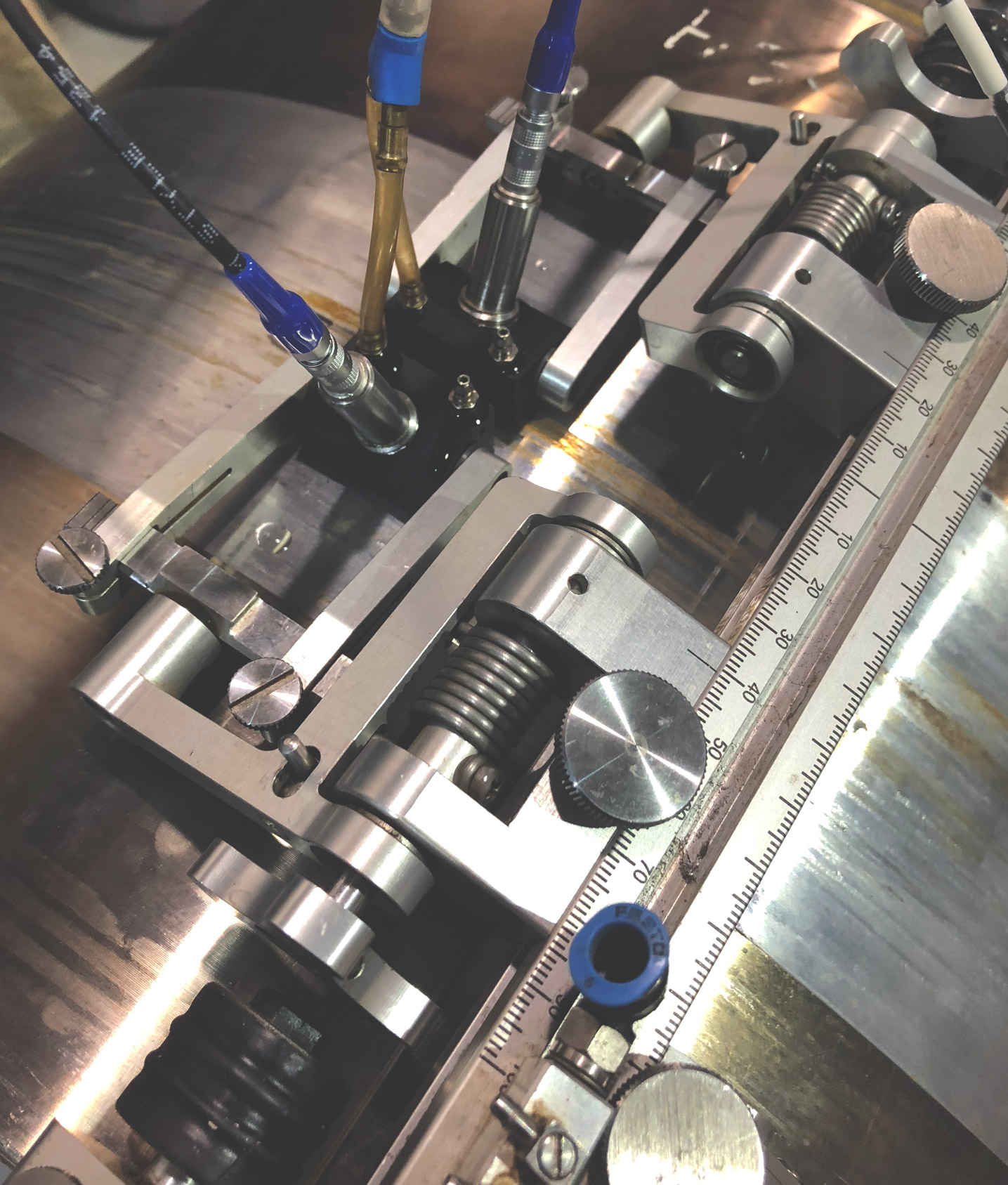
Automated Ultrasonic Testing (AUT) consists of a motorized inspection system (the scanner), which manipulates the probes while tracking their position the entire time.
Thanks to recent innovations in both software and robotics, AUT systems equipped with multiple PAUT probes, cameras, and sensors are now available.
One of the first applications in which this technique achieved worldwide acceptance and deployment has been the inspection of pipeline circumferential welds in lieu of radiography. In this case, the scanner generally includes two PAUT probes, a pair of TOFD (Time-of-Flight Diffraction) probes, as well as two pairs of ‘transverse’ probes.
In addition to weld inspection, the AUT technique is ideal for corrosion detection on difficult to access structures. It can also provide 100% coverage with an increased production of resulting data in comparison to traditional methods.
Advantages :
Conventional Ultrasonic Testing (CUT) uses a probe comprised of a piezoelectric element capable of deforming and generating high frequency acoustic waves that travel a specific velocity dependent on the material. The result is an A-scan on the UT instrument’s display. Analysis of this A-scan display allows for the evaluation and interpretation of the specimen under examination.
Conventional Ultrasonic inspection is primarily used for thickness measurement, weld inspection, and for lamination and corrosion detection. Multiple CUT modes exist: reflection (Pulse-Echo), Pulse-Receive (Dual) and Through Transmission (TT). Pulse-Echo is most common.
Advantages:

Time-Of-Flight Diffraction (TOFD) is a technique based on an ultrasonic wave’s travelling time, or ‘time of flight’, and the diffraction produced by the extremities of the discontinuity. TOFD consists of a pair of CUT transducers on angled wedges defined to produce longitudinal waves. A pair of probes face each other: one pulses while the other receives, and are separated by a known distance that ensures coverage of the desired zone.
TOFD data analysis is performed with unrectified A-Scans and a B-Scan with a greyscale colour palette.
TOFD is recognized for its high level of accuracy and precision regarding sizing and is often used as a complement to the Phased Array method.
Advantages:
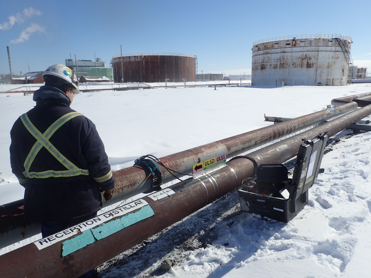
Guided Wave Inspection (GW) is a branch of ultrasonic inspection that is distinguished by wave propagation in the direction parallel to the surface, usually at low frequency (between 20 kHz-100 kHz). This makes it an NDT technique that allows long distances to be assessed from a single inspection point without external coupling input.
GW id primarily used for the detection of corrosion on process piping and on the petrochemical pipeline, both above and below ground. However, its field of application is very wide, and this technology is also used to inspect piping in the field of construction (e.g. heat exchangers, water pipes), mining (e.g. water treatment network), nuclear (e.g. feed tubes). To conduct a survey, a transducer collar is installed on the pipe and an acquisition system is used to collect the data. Analysis of these data makes it possible to detect variations in thickness in order to locate very precisely (±2”) critical areas to be further investigated by other complementary NDT methods.
The range of waves varies according to the type of material, the surface condition and the configuration of the piping, but generally, a distance of 30 metres (100 feet) on each side of the collar can be inspected in a single measure, only having access to a short section of the piping. Thanks to this feature, it is possible to quickly inspect 100% of the volume of the piping including when it is difficult to access (e.g. buried pipe, high-rise pipe, insulated pipe, with a coating).
Nucleom distinguishes itself from other competitors by its strong involvement in the research and development of this technology, in particular by employing researchers within its team and by working in partnerships with its industrial suppliers and a laboratory specialized in GW.
Advantages
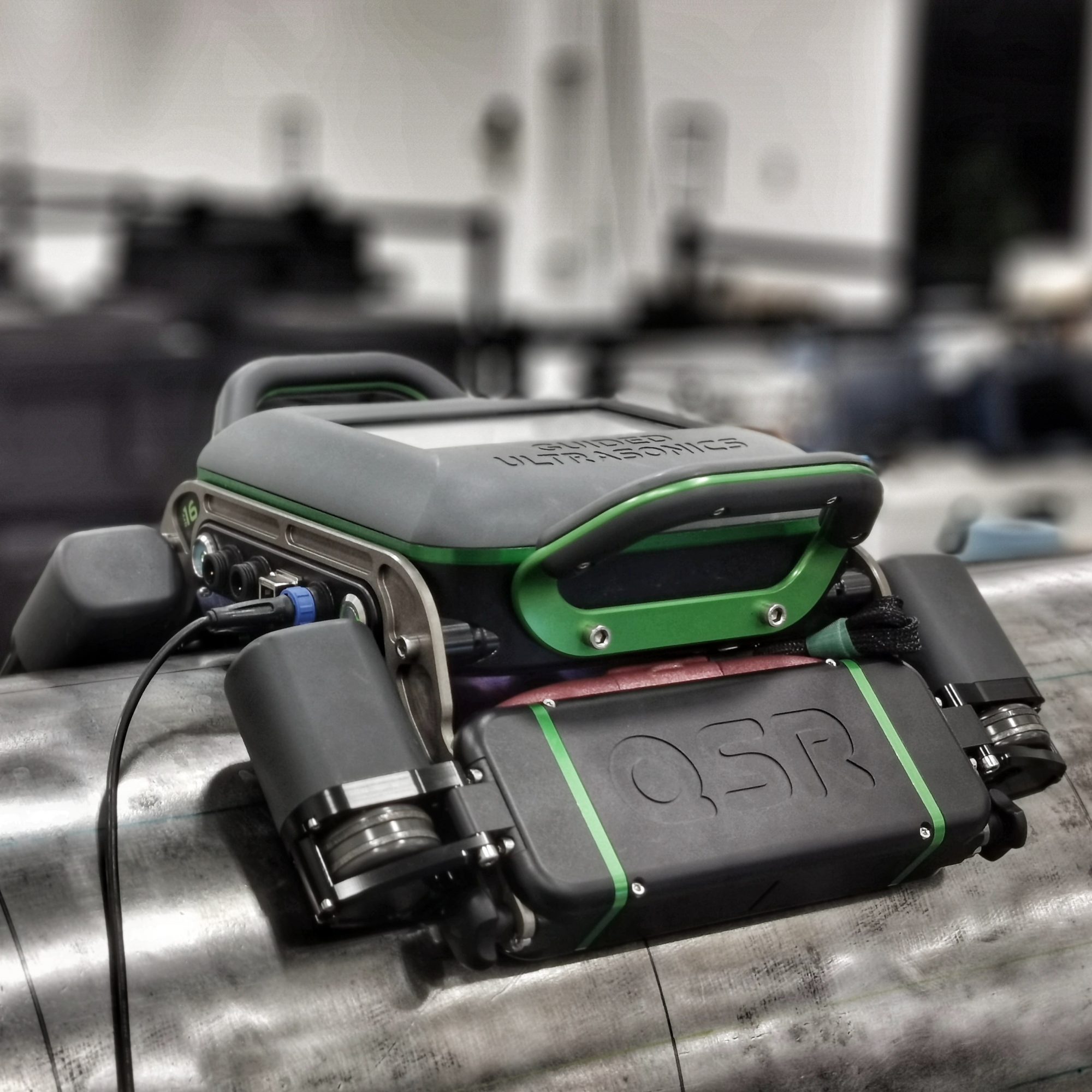
The Quantitative Short-Range (QSR) Guided Wave Inspection (GW) is a variant of the GW inspection that is distinguished by a pitch catch wave propagation in the circumferential direction of a pipe, generally at a higher frequency (between 100 kHz-500 kHz) than the long-range GW. The main advantages of measuring the minimum residual thickness by QSR are that it is quantitative and covers 100% of the pipe (including under supports or other inaccessible areas).
The QSR is mainly used for measuring corrosion under pipes and more particularly for circumferential areas that are inaccessible, for example in the critical case of a support or a pipe resting on the ground. Unlike most other ultrasonic measurement techniques, coupling is done without contact using two electromagnetic acoustic transducers (EMAT), which greatly facilitates measurements and limits possible operator-related errors. To inspect piping, the QSR is deposited on the pipe and semi-automatic acquisition process is initiated from a computer. Electrical motors with mechanical and optical encoding and EMATs generate and record waves at all digitization points of the pipe. Thereafter, a semi-automated frequency analysis determines the cut-off frequency at each inspection point, which is inversely proportional to the residual pipe thickness.
To date, QSR can be used on NPS 8- to NPS 24- thick ¼” to ½ “diameter, carbon steel, even with the think coating. However, this technology is very new and other pipe diameter and thickness will soon be possible with the QSR.
Nucleom distinguishes itself from other competitors by its strong involvement in the research and development of this technology, particularly by employing researchers within its team and by working in partnership with its industrial suppliers and a laboratory specialized in GW.
Advantages:
Full Matrix Capture (FMC) is an advanced data acquisition and reconstruction method using PAUT probes. FMC is based on the synthetic focusing principle and is processed by algorithms resulting in a picture-like visualization of the area under examination.
The basic operation behind the method is that each element of the entire probe aperture emits an ultrasound in the material while all the elements record the returned signal. All this data is then processed and received signals are organized as a matrix.
The resulting matrix can be processed by algorithms to produce the image. This process is called the Total Focusing Method (TFM).
The data reconstruction happens on a defined zone where each point is constructed from the information recorded by each probe element while taking the various delays into consideration. TFM comes in multiple modes depending on the nature of the reflected ultrasonic wave, which is designated by a combination of the letters T (transverse) and L (longitudinal): TT, TTT, TTL, LLL, etc.
Advantages:
 Are you facing inspection challenges?
Our team of specialists is here to assist you. Discover how our services can effectively and professionally address your inspection needs.